Cutting Fluids in Metalworking: How to Choose and Maintain a Cooling System
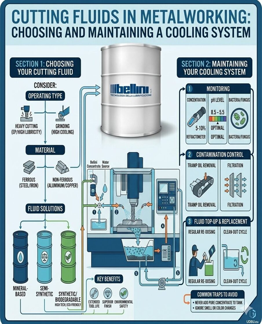 Cutting Fluids in Metalworking: How to Choose and Maintain a Cooling System
Cutting fluids are one of the key factors ensuring stable and efficient metalworking. Properly selected and maintained coolant helps extend tool life, improve surface quality of parts, and reduce production costs.
In this article, we will look at the main types of cutting fluids, how to choose the right one, and how to properly maintain a cooling system in a manufacturing environment.
Why Cutting Fluids Are Important in Metalworking
During milling, drilling, turning, and grinding operations, a large amount of heat and friction is generated in the cutting zone. Cutting fluids perform several important functions:
reduce temperature in the cutting area
decrease friction between the tool and the workpiece
help remove chips
protect parts and equipment from corrosion
improve surface finish quality
Without effective cooling, tools wear out much faster and machining quality can become inconsistent.
Main Types of Cutting Fluids
Several types of cutting and cooling fluids are used in metalworking.
Oil-Based Cutting Fluids
These fluids are based on mineral or synthetic oils.
Advantages:
excellent lubrication properties
strong tool protection
suitable for heavy cutting operations
Disadvantages:
lower cooling capacity
may produce smoke and odor
They are commonly used in threading, broaching, and deep cutting operations.
Emulsions (Oil-in-Water)
This is the most commonly used type of cutting fluid in CNC machines.
Advantages:
good cooling performance
versatile application
relatively low cost
Disadvantages:
requires regular concentration monitoring
bacteria may develop
Semi-Synthetic Fluids
These fluids combine the properties of oils and water-based solutions.
Advantages:
good cooling performance
adequate lubrication
reduced bacterial growth risk
They are widely used in modern CNC manufacturing.
Synthetic Cutting Fluids
These are fully water-soluble fluids without mineral oil.
Advantages:
excellent cooling performance
cleaner working environment
high stability
Disadvantages:
weaker lubrication in heavy-duty operations
They are commonly used in high-speed machining and grinding.
How to Choose the Right Cutting Fluid
Several important factors should be considered when selecting a cutting fluid.
Workpiece Material
Different metals require different fluid characteristics.
aluminum requires good anti-adhesion properties
stainless steel requires stronger lubrication
titanium requires stability at high temperatures
cast iron requires effective chip removal
Type of Machining
Different operations require different cooling and lubrication properties.
Milling – efficient cooling is essential
Turning – balance between cooling and lubrication
Grinding – intensive cooling is required
Deep drilling – lubrication and chip evacuation are critical
Machine Requirements
Many modern CNC machines require fluids with low foaming characteristics and stable emulsions.
Environmental and Workplace Safety
Modern companies increasingly choose cutting fluids that are:
low in toxicity
free from chlorine compounds
free from harmful additives
This improves working conditions for operators and reduces environmental impact.
Proper Maintenance of the Cooling System
Even high-quality fluids quickly lose their properties without proper maintenance.
Concentration Control
Emulsion concentration should be regularly checked using a refractometer.
Too low concentration may cause:
corrosion
bacterial growth
Too high concentration may cause:
foaming
increased fluid consumption.
Chip Filtration
Metal chips contaminate the fluid and accelerate tool wear.
It is recommended to use:
magnetic separators
belt filters
cyclone filtration systems.
Bacteria Control
Bacteria and fungi may cause:
unpleasant odors
deterioration of fluid properties
skin irritation for machine operators
Prevention includes:
regular circulation or mixing of the fluid
maintaining the correct concentration
using biocides when necessary.
System Cleaning
Even with regular maintenance, the cooling system should be fully cleaned every 6–12 months:
drain the old fluid
clean the tank and pipelines
remove deposits and sludge
refill with fresh cutting fluid
Common Mistakes When Using Cutting Fluids
Manufacturing environments often encounter the following issues:
using an unsuitable cutting fluid
lack of concentration monitoring
infrequent system cleaning
mixing different types of fluids
These problems may lead to faster tool wear, inconsistent machining quality, and increased production costs.
Conclusion
Cutting fluids play a critical role in metalworking. Proper fluid selection and regular system maintenance help:
extend tool life
improve part quality
reduce production costs
ensure stable CNC machine operation
If you are looking for high-quality cutting fluids for metalworking, explore the Bellini product range here:
https://www.udbu.eu/product/bellini/
Bellini offers professional solutions for metalworking companies, ensuring high efficiency, stable emulsions, and safer working conditions.
Completion of Compressor Equipment Installation
 Completion of Compressor Equipment Installation
The installation of compressor equipment has been successfully completed at Malnavas koledža. The system is intended to support the operation of various technical devices and training equipment.

As part of the project, the compressor was installed and connected, the system was tested, and the equipment was adjusted to ensure stable and safe operation. The new system will provide the necessary compressed air pressure for different technical devices and will improve the efficiency of practical training activities.
Malnavas koledža is an educational institution that places strong emphasis on practical training for students, particularly in the fields of engineering, transport, and agricultural mechanization.
The implementation of this project contributes to the development of the college’s technical infrastructure and helps create modern learning conditions for students.
Industry 4.0 in Metalworking: Digital Manufacturing Architecture and Practical Implementation Benefits
 Industry 4.0 in Metalworking: Digital Manufacturing Architecture and Practical Implementation Benefits
1. Architecture of a Digital Metalworking Enterprise
In the context of metalworking, Industry 4.0 represents the development of a unified cyber-physical system (CPS) integrating:
-
CNC machines
-
CNC and PLC control systems
-
IIoT sensors
-
MES/ERP systems
-
CAD/CAM/PLM solutions
-
Analytics platforms
-
Cloud or edge infrastructure
The core principle is end-to-end data integration from the shop floor to the top floor.
A typical architecture includes:
Equipment Level (Level 0–1)
CNC machines, robots, measurement systems, vibration sensors, temperature sensors, spindle load monitoring, and tool condition sensors.
Data Acquisition Level (Level 2)
IIoT gateways, OPC UA, MTConnect, Modbus TCP/IP.
Manufacturing Operations Level (Level 3)
MES system:
-
Production dispatching
-
OEE monitoring
-
Order management
-
Full traceability
Business Analytics Level (Level 4)
ERP, BI systems, financial planning, KPI analytics.
2. CNC Integration into the Digital Ecosystem
Modern CNC machines act as high-frequency data sources, providing:
-
Spindle load
-
Cycle time
-
Axis acceleration
-
Drive currents
-
Tool condition data
-
Alarm and fault events
The key objective is not just data collection, but:
-
Normalization
-
Synchronization
-
Aggregation
-
Contextual interpretation
Without MES-level integration, raw machine data does not create business value.
3. OEE and Digital Production Transparency
Industry 4.0 enables the transition from subjective reporting to automated calculation of:
-
Availability
-
Performance
-
Quality
Practical impact:
-
Reduction of hidden downtime
-
Bottleneck identification
-
Accurate capacity planning
Digitally mature enterprises typically achieve a 10–25% OEE increase after implementation.
4. Predictive Maintenance Using Machine Learning
In metalworking, the main sources of unplanned downtime include:
-
Spindle wear
-
Bearing degradation
-
Tool wear
-
Overheating
-
Vibration deviations
ML algorithms analyze:
-
Vibration spectra
-
Temperature trends
-
Current anomalies
-
Cycle time variations
Results:
-
Up to 40% reduction in emergency downtime
-
Transition from scheduled to condition-based maintenance
-
Reduced spare parts costs
5. Digital Twins in Technological Processes
In metalworking, digital twins are used for:
-
Cutting parameter simulation
-
Toolpath optimization
-
Thermal deformation analysis
-
Tool wear prediction
Integration with CAM systems enables:
-
Program verification before execution
-
Reduced setup time
-
Lower scrap rates during new batch launches
This is particularly critical for high-precision and small-batch production.
6. Robotics and Autonomous Manufacturing Cells
Industry 4.0 in metalworking includes:
-
Robotic loading and unloading
-
Automatic pallet changing
-
Flexible Manufacturing Systems (FMS)
Benefits:
-
24/7 operation without increasing headcount
-
Stable and repeatable quality
-
Reduced dependency on human factors
The average ROI of a robotic cell is 18–36 months in serial production environments.
7. Industrial Network Cybersecurity
Digitalization increases the attack surface:
-
Remote CNC access
-
Cloud service integration
-
ERP/MES connectivity to machines
Required measures include:
-
IT/OT network segmentation
-
Role-based access control (RBAC)
-
Event logging
-
Regular firmware and software updates
-
Data transmission protocol audits
A cybersecurity incident can result in complete production shutdown.
8. Implementation Economic Model
Investment areas typically include:
-
Equipment modernization
-
MES implementation
-
IIoT infrastructure
-
Analytics solutions
-
Workforce training
Financial benefits:
-
Scrap reduction
-
Downtime reduction
-
WIP inventory optimization
-
Faster order fulfillment
-
More accurate profitability analysis
In the B2B segment, digital traceability significantly increases customer trust.
9. Equipment Readiness for Industry 4.0: The Strategic Starting Point
The transition to digital manufacturing is impossible without a solid technological foundation. If existing machines do not support OPC UA, MTConnect, or reliable data transmission, digitalization will be fragmented and costly.
UDBU supplies modern metalworking machines designed to meet Industry 4.0 requirements:
-
MES and ERP integration capability
-
IIoT sensor connectivity readiness
-
Digital machine condition monitoring
-
Remote diagnostics capability
-
Compatibility with robotic manufacturing cells
Investing in Industry 4.0-ready equipment enables companies to:
-
Reduce implementation timelines
-
Minimize infrastructure adaptation costs
-
Reach target OEE levels faster
-
Ensure scalable production growth
If your company’s strategy includes increasing digital maturity and strengthening competitiveness in the B2B market, selecting the right machine park is a fundamental step.
Contact UDBU specialists to select machines ready for operation within an integrated digital manufacturing environment.
Conclusion
Industry 4.0 in metalworking is not about isolated technology upgrades — it is a systematic transformation of manufacturing architecture.
Companies that:
-
Ensure end-to-end data integration
-
Implement MES and predictive analytics
-
Automate production cells
-
Invest in cybersecurity and modern equipment
gain sustainable competitive advantages through transparency, controlled cost structures, and predictable product quality.
Latest Trends in Combating Oil Aerosols in Manufacturing Workshops
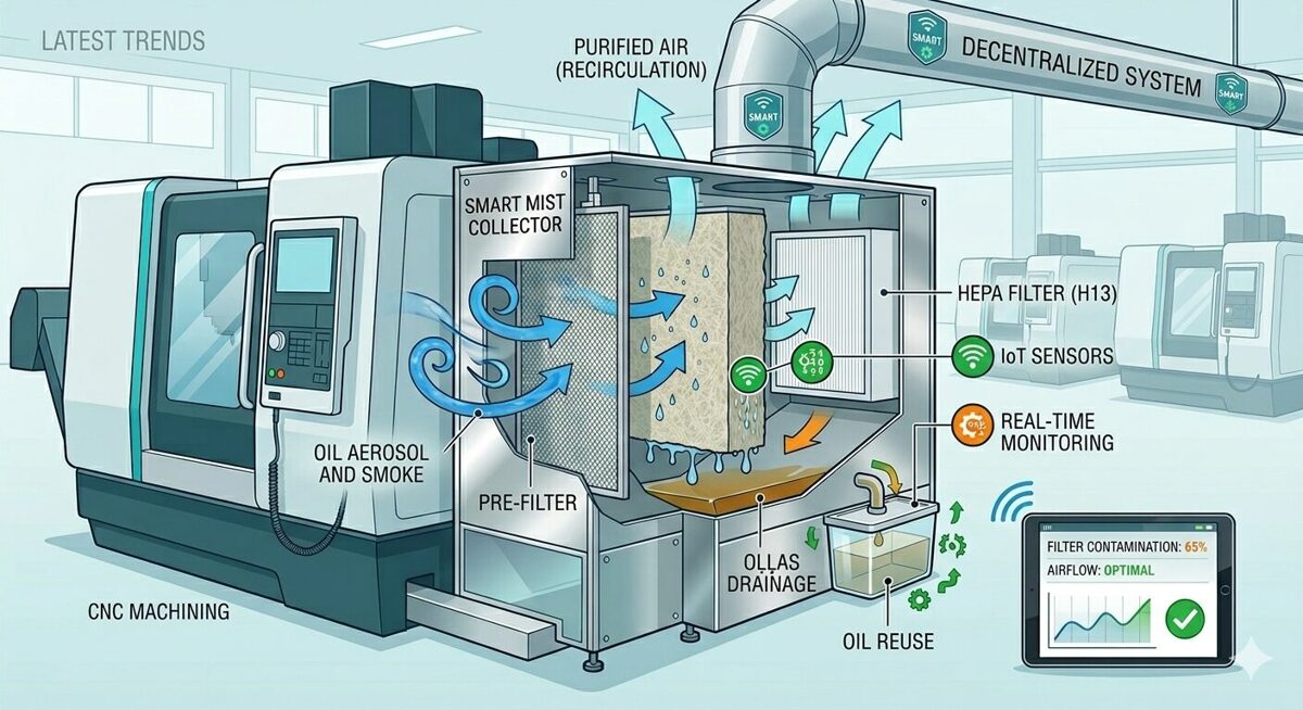 Latest Trends in Combating Oil Aerosols in Manufacturing Workshops
Metalworking requires high precision and productivity, but it also creates significant challenges in maintaining air quality. One of the main issues is oil aerosols generated when using cooling and lubricating fluids in CNC and other metalworking machines. These microscopic particles can negatively affect employee health, equipment longevity, and the overall working environment.
Today, air purification technologies are rapidly evolving, offering more efficient, cost-effective, and environmentally friendly solutions.
1. Smart Filtration Systems and Automation
The new generation of oil mist collectors is equipped with sensors and automatic control functions. They can:
-
adjust performance according to pollution levels;
-
notify operators about filter wear;
-
optimize energy consumption.
This approach reduces downtime risks and ensures stable air quality without manual adjustments.
2. Multi-Stage Filtration Technologies
For effective oil aerosol removal, combined filtration systems are increasingly used:
-
mechanical pre-filtration for larger particles;
-
coalescing filters to combine oil droplets;
-
fine filtration elements for final air polishing.
Such systems can achieve more than 99% contaminant capture efficiency, significantly improving the working environment.
3. Recirculation of Cleaned Air
Energy efficiency is one of the main goals of modern industry. Advanced solutions allow companies to:
-
return cleaned air back into the workshop;
-
reduce heating and ventilation costs;
-
maintain a stable indoor climate.
This is especially important in colder regions, where heat loss can result in substantial expenses.
4. Sustainable Filtration Materials
Manufacturers are increasingly using:
-
long-life filtration materials;
-
recyclable components;
-
designs that allow easy maintenance.
This reduces operational costs and minimizes waste.
5. Integration with Occupational Safety Systems
Air quality monitoring is now integrated into overall workplace safety systems. This includes:
-
real-time pollution monitoring;
-
automated alerts;
-
improved employee health protection.
Clean air is no longer an added benefit — it is a production standard.
Practical Solution: PrecitoniX OMM 150 Oil Mist Collector
As an example of a modern and efficient solution, the PrecitoniX OMM 150 Oil Mist Collector, available from UDBU, demonstrates how compact systems can deliver powerful performance in metalworking environments.
Manufactured by PrecitoniX, this model is designed for metalworking machines that require compact yet highly efficient oil aerosol removal. It provides:
-
effective oil mist extraction directly from the machine’s working area;
-
multi-stage filtration;
-
simple installation and maintenance;
-
improved workplace air quality and equipment protection.
More information about the product:
https://www.udbu.eu/produkti/item/instrumenti/precitonix-omm-150-ellas-miglas-savacejs/
Conclusion
Combating oil aerosols in modern metalworking facilities is based on:
-
automated and intelligent filtration systems;
-
multi-stage air purification;
-
energy-efficient air recirculation;
-
sustainable materials;
-
integrated occupational safety strategies.
By implementing modern oil mist collection systems, companies not only improve working conditions but also reduce operating costs and enhance long-term production efficiency.
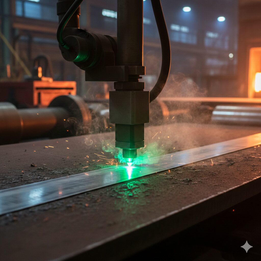
Laser Welding of Thin Materials: Advantages, Limitations, and Comparison with TIG/MIG

Laser Welding of Thin Materials: Advantages, Limitations, and Comparison with TIG/MIG
Laser welding is one of the most advanced technologies for joining thin metals (0.1–3 mm). It is widely used in mechanical engineering, electronics manufacturing, medical equipment production, and the automotive industry, where precision, minimal distortion, and high aesthetic quality are essential.
Due to its concentrated energy, a laser produces a narrow and deep weld seam with a minimal heat-affected zone (HAZ), which is especially important when working with thin sheets.
Main Laser Welding Methods
Heat Conduction (Conduction) Welding
Energy is evenly distributed across the surface without creating a “keyhole” effect. Suitable for very thin materials and applications with high aesthetic requirements.
Deep Penetration (Keyhole) Welding
High power density creates a vapor channel, enabling a deep and narrow weld seam with high strength.
Pulsed Laser Welding
Short pulses allow precise control of heat input. Ideal for micro-components and precision parts.
Hybrid Laser–Arc Welding
Combines laser and arc technologies to improve stability and compensate for joint gaps.
Advantages of Laser Welding
-
Minimal heat-affected zone
-
Very high precision
-
Low distortion
-
High processing speed
-
Clean and aesthetic weld seam
-
Easy integration into automated and CNC systems
Limitations
-
High equipment cost
-
Strict requirements for part preparation
-
Sensitivity to gaps and surface contamination
-
Need for skilled operators
Comparison: Laser Welding vs TIG/MIG for Thin Materials
| Parameter | Laser Welding | TIG Welding | MIG Welding |
|---|---|---|---|
| Material thickness | 0.1–3 mm (optimal) | from 0.5 mm | from 0.8 mm |
| Heat input | Low, concentrated | Medium | Higher |
| Heat-affected zone | Minimal | Medium | Wider |
| Burn-through risk | High if improperly set | Medium | Increased for thin materials |
| Sheet distortion | Minimal | Possible | Often significant |
| Welding speed | Very high | Low–medium | Medium–high |
| Weld precision | Very high | High | Medium |
| Weld aesthetics | Usually no post-processing required | Often requires cleaning | Usually requires cleaning |
| Automation | Excellent integration with CNC and robotics | Limited | Suitable for robotic systems |
| Edge preparation requirements | High | Medium | Less critical |
| Equipment cost | High | Medium | Lower than TIG |
| Operating costs | Low in serial production | Medium | Medium |
Conclusion
If the priority is precision, minimal distortion, and high productivity in serial manufacturing, laser welding is the most technologically and economically efficient long-term solution.
TIG welding remains a flexible option for small batches and repair work, while MIG welding is better suited for thicker materials or less demanding structural applications.
Laser Machine Optics Diagnostics: When to Replace Lenses and How It Affects Accuracy
 Laser Machine Optics Diagnostics: When to Replace Lenses and How It Affects Accuracy
The optics in a laser machine are the heart of the system, guiding the laser beam onto the material. Over time, the quality of lenses and mirrors can deteriorate, leading to reduced cutting accuracy, poorer edge quality, and even defects in parts. It is important to be able to diagnose the condition of the optics, understand when lens replacement is needed, and how preventive maintenance affects the final results.
Why Optics Wear Out
The optics in a laser head are affected by:
-
Thermal stress, especially during intensive production cycles.
-
Dust and debris – particles on the lenses reduce beam transmission.
-
Mechanical impact – improper replacement of protective lenses, bumps, and vibrations.
-
Humidity and aggressive workshop environments.
These factors cause loss of beam power and focus degradation, leading to wider cutting gaps, uneven lines, inconsistent cutting depth, and increased energy consumption to achieve the same results.
How to Diagnose Lens Condition
Visual inspection: check the lens when the machine is off. Look for cloudy or matte surfaces, burn marks, dark spots, or color changes. Even minor defects can indicate beam defocusing and reduced power.
Test cuts: perform several identical cuts on the same material sheet at reduced power. If quality declines faster than usual, the lens may be dirty or damaged.
Focus zone temperature monitoring: excessive heat at the focus point indicates the lens is not properly dispersing the beam, which can damage other components.
Examples: How Clean vs. Worn Optics Affect Performance
Consider real equipment such as Golden Laser cutting machines – modern systems with fiber laser sources and high-precision heads for sheet and tube processing. These machines provide high accuracy, automation, and stability when properly maintained. Even in these systems, dirty or damaged lenses can reduce cutting quality by 5–20% (depending on the metal type and power). Regular cleaning and replacement of lenses ensures the manufacturer’s specified precision and processing speed are maintained.
When Lens Replacement Is Needed
Lenses should be replaced in the following cases:
-
Visible wear: lens is cloudy, scratched, or otherwise damaged.
-
Significant decline in cutting quality at stable machine settings.
-
Increased defects on parts that cannot be corrected by cleaning or adjustments.
-
After mechanical damage or accidents.
In many industrial machines, optics are replaced according to operating hours, even if no visible defects are present, to prevent downtime.
Maintenance and Prevention
To extend lens lifespan:
-
Use protective lenses, which are cheaper to replace than the main optics.
-
Regularly blow the system with dry compressed air.
-
Keep the workshop environment clean – less dust extends optical life.
-
Keep a log of lens condition and maintenance intervals.
Impact on Accuracy and Productivity
When lenses are in good condition:
-
Beam is properly focused
-
Cutting geometry is precise
-
Less material waste
-
Energy savings
-
Stable cutting cycles
When lenses are dirty or damaged:
-
Cutting quality deteriorates
-
Energy consumption increases
-
Equipment wears faster
-
Part defects may occur
Conclusion
Optics diagnostics is not just a formality; it is a key factor in laser processing quality and stability. Timely lens replacement prolongs machine life and maintains high industrial precision.
Do you want to optimize your laser machine’s optical system, receive diagnostics advice, or select original lenses and components?
Contact our experts – we will provide the optimal maintenance plan and original optical components for your equipment.
Fill out the inquiry now and get a free initial consultation on optics diagnostics!
Laser Descaling of Rolled Metal: Mechanisms, Operating Modes, and Comparison with Chemical Methods
Laser Descaling of Rolled Metal: Mechanisms, Operating Modes, and Comparison with Chemical Methods
Introduction
Descaling rolled metal is one of the key tasks in the metallurgical and mechanical engineering industries. Scale is a thin oxide layer that forms on the surface of metals during heating in the production process. It reduces coating adhesion, worsens the quality of welded joints, and accelerates corrosion.
Traditional cleaning methods include mechanical processing (brushes, grinding) and chemical treatment (acid baths, alkaline solutions). These methods have their limitations: mechanical cleaning can damage the metal, while chemical methods create environmental risks and require waste disposal.
A modern solution is laser cleaning of rolled metal. This technology allows scale removal with high precision, minimal thermal impact, and without the use of aggressive chemicals.
Mechanisms of Laser Cleaning
Laser cleaning is based on the interaction of high-intensity laser radiation with the surface layer of scale. The main mechanisms are:
-
Ablation
A laser pulse vaporizes the scale, leaving the metal untouched. The efficiency of ablation depends on the laser wavelength and energy density.
Application: cleaning thin oxide films on steel and aluminum. -
Thermal Expansion
The difference in thermal expansion coefficients between the metal and the scale leads to scale detachment when heated by the laser.
Advantage: suitable for thick scale layers, minimal impact on the base metal. -
Plasma Interaction
At high power levels, localized plasma forms, which destroys the scale at the microscopic level.
Advantage: improves removal efficiency even on uneven surfaces.
The effectiveness of laser cleaning depends on the laser type (CO₂, fiber, diode), wavelength, power, pulse duration, and processing speed.
Laser Cleaning Operating Modes
To achieve optimal results, different laser operating modes are used:
| Mode | Features | Application |
|---|---|---|
| Pulsed | Short, high-intensity pulses; minimal heating of the metal | Micron-level cleaning, spot defects |
| Continuous (CW) | Constant radiation; high power | Thick scale layers, uniform coverage |
| Scanning | The laser spot moves across the surface | Cleaning large areas with minimal thermal impact |
Parameter Adjustment
-
Laser power: high power increases cleaning speed but may overheat the metal.
-
Pulse frequency: determines the uniformity of scale removal.
-
Scanning speed: too slow increases thermal impact, too fast reduces effectiveness.
The choice of mode depends on the type of metal, scale thickness, and surface quality requirements.
Comparison with Chemical Methods
Laser cleaning is often compared with acid and alkaline methods of scale removal. The main comparison criteria are:
| Parameter | Laser Cleaning | Chemical Treatment |
|---|---|---|
| Impact on metal | Minimal; metal retains its strength | Structural changes and corrosion possible |
| Environmental impact | High environmental safety; no chemical waste | Moderate; requires disposal of chemical solutions |
| Speed | High when automated | Moderate; often requires immersion and rinsing |
| Precision | Micron-level | Limited; difficult for localized treatment |
| Operating cost | High initial investment in laser equipment | Lower, but with chemical consumption and waste handling |
| Maintenance | Minimal after installation | Regular solution replacement and equipment cleaning |
Conclusion: laser cleaning outperforms in environmental safety, precision, and speed but requires higher initial investment.
Advantages and Limitations of Laser Cleaning
Advantages:
-
High precision and control over cleaning depth.
-
Possibility of automation and integration into production lines.
-
No chemical reagents and minimal waste.
-
Suitable for complex and sensitive surfaces.
Limitations:
-
High equipment cost.
-
Higher energy consumption compared to chemical methods.
-
Requires qualified personnel to adjust laser parameters.
Application Examples
-
Metallurgy: removal of scale from sheet metal before coating application.
-
Automotive industry: preparation of parts for welding and painting.
-
Electrical engineering: cleaning copper and aluminum surfaces for contact connections.
-
Equipment repair: removal of corrosion and oxide layers from turbines, machine tools, and presses.
Conclusion
Laser descaling of rolled metal is becoming the standard in modern industrial processes due to its precision, environmental safety, and automation capability. The correct choice of operating mode, power adjustment, and pulse frequency allows high efficiency without damaging the metal.
Comparison with chemical methods shows that laser cleaning is not only safer for the environment but also economically justified in large-scale industrial production. In the context of increasing quality and environmental requirements, laser cleaning of rolled metal represents an investment in long-term efficiency and reduced production risks.
Magnetic Abrasive Finishing: Principles and Application Areas
 Magnetic Abrasive Finishing: Principles and Application Areas
What is Magnetic Abrasive Finishing (MAF)
Magnetic Abrasive Finishing (MAF) is a high-precision surface finishing method in which a magnetic field controls the abrasive tool. A magnetic field is created in the working zone, forming a so-called magnetic abrasive brush made of ferromagnetic particles and abrasive grains. This flexible brush gently acts on the surface, removing micro-irregularities and surface defects.
The method is particularly effective for internal channels and complex geometries where conventional machining is difficult.
Operating Principle
The MAF process is based on the interaction of three components:
-
Magnetic field – generated by permanent magnets or electromagnets.
-
Magnetic abrasive powder – mixture of ferromagnetic particles and abrasives (Al₂O₃, SiC, diamond).
-
Relative motion – ensures material removal.
Particles align in chains under the magnetic field, forming an elastic working zone adaptable to surface geometry.
Tasks Solved by MAF
-
Surface roughness reduction to Ra 0.01–0.05 μm
-
Micro-burr removal
-
Polishing of internal channels
-
Improvement of fatigue strength
-
Surface preparation before coating
Application Areas
Aerospace, medical manufacturing, automotive industry, mold and die production.
Advantages
-
Complex geometry processing
-
Minimal thermal impact
-
High repeatability
-
No rigid tool contact
-
Automation capability
Limitations
-
Not suitable for heavy material removal
-
Requires precise magnetic field control
-
High equipment cost
Future Development
-
Integration into automated lines
-
Hybrid technologies (MAF + electrochemical finishing)
-
Intelligent parameter control
-
Finishing of additively manufactured parts
Top 5 Tube Laser Brands in 2026: Ranking, Key Advantages, and Buying Guide

Top 5 Tube Laser Cutting Machine Brands 2026: Ranking, Key Advantages & Buying Guide
Tube laser cutting machines have become an essential part of modern metal fabrication across Lithuania, Latvia, and Estonia. As demand grows for high-precision tube processing, manufacturers are increasingly investing in automated fiber laser systems that reduce material waste, lower labor costs, and improve overall production quality.
In this UDBU blog article, we review the Top 5 tube laser cutting machine brands in 2026, compare their technical capabilities, and provide practical guidance for choosing the right solution for the Baltic market.
Why Tube Laser Cutting Is Essential in Modern Manufacturing
Fiber tube laser technology enables:
-
High-precision cutting of round, square, and rectangular tubes
-
Complex 2D and 3D contour processing without additional tooling
-
Minimal heat-affected zones and reduced material deformation
-
Faster production cycles compared to traditional mechanical methods
-
Automated loading systems and integration with ERP/MES software
SEO keywords: tube laser cutting, fiber laser tube cutter, precision tube processing, automated tube cutting, industrial laser Baltic States.
Top 5 Tube Laser Cutting Machine Brands 2026
| Rank | Brand / Model | Laser Power (W) | Max Tube Diameter (mm) | Wall Thickness (mm) | Key Advantages |
|---|---|---|---|---|---|
| 1 | Golden Laser S12 Plus | ~3000–4000 | up to 120 | 10–15 | High automation, 3D cutting capability, excellent price-performance ratio |
| 2 | Baison Laser All-round Tube Cutter | 1500–6000 | up to 220 | 0.8–10 | Wide power range, versatile applications |
| 3 | TRUMPF TruFiber 3001 | ~3000 | up to 152 | 4–8 | Premium quality, Industry 4.0 integration |
| 4 | Bystronic ByTube Star 130 | ~4000 | up to 130 | 10–15 | Swiss precision, robust construction |
| 5 | LightObject Pro Fiber Tube Cutter | ~3000 | up to 210 | 5–15 | User-friendly, suitable for medium production volumes |
1. Golden Laser — Leader in Automation and Value
Golden Laser tube laser cutting solutions, especially the S12 Plus, offer an optimal balance between automation, performance, and investment cost for Baltic manufacturers.
Key advantages:
-
Automatic tube loading system
-
Advanced 3D cutting capabilities
-
Compact and stable machine design
-
Energy-efficient fiber laser technology
Ideal for: metal fabrication companies in Lithuania, Latvia, and Estonia seeking a modern, automated, and cost-effective solution.
SEO keywords: Golden Laser tube cutter, fiber tube laser Baltic, automated metal cutting Lithuania.
2. Baison Laser — Flexible and Powerful Solutions
Baison Laser offers machines with a broad power range (1.5–6 kW) and the ability to process larger diameter tubes.
Key advantages:
-
High flexibility across different materials and profiles
-
Suitable for complex geometries
-
Strong solution for small and medium-sized manufacturers
3. TRUMPF — German Premium Engineering
TRUMPF TruFiber systems are known for precision, reliability, and seamless integration with digital manufacturing processes.
Key advantages:
-
Exceptional edge quality
-
Long-term operational reliability
-
Full Industry 4.0 compatibility
Ideal for: large-scale and serial production environments.
4. Bystronic — Swiss Precision and Durability
Bystronic ByTube Star 130 delivers high-precision cutting and robust mechanical stability for demanding production lines.
Key advantages:
-
Stable and durable construction
-
High-quality cutting results
-
Integration with production management systems
5. LightObject — Practical Mid-Range Solution
LightObject provides reliable and user-friendly tube laser systems for medium production needs.
Key advantages:
-
Easy operation and programming
-
Balanced price-to-performance ratio
-
Suitable for medium-volume manufacturing
How to Choose a Tube Laser Cutting Machine in the Baltic States
1️⃣ Maximum Tube Diameter
Select a machine based on your largest processed profile.
2️⃣ Laser Power
-
~3000 W — suitable for thin to medium wall thickness
-
≥4000 W — required for thicker materials and intensive production
3️⃣ Automation Level
Automatic loading and ERP/MES integration significantly increase productivity.
4️⃣ Local Service and Support
Reliable service in Lithuania, Latvia, and Estonia minimizes downtime.
5️⃣ ROI Evaluation
Consider installation, operating, maintenance, and energy costs when calculating total investment return.
Conclusion
Investing in a modern fiber tube laser cutting machine significantly improves production accuracy, efficiency, and long-term cost performance in the Baltic market.
In the 2026 ranking, Golden Laser stands out as the optimal solution for companies seeking high automation, 3D cutting capability, and a strong price-performance balance. Meanwhile, Baison, TRUMPF, Bystronic, and LightObject provide alternative solutions tailored to different production scales and budget levels.
Choosing the right tube laser system is not just a technical decision — it is a strategic investment in your company’s growth and long-term competitiveness.
Intelligent Cooling Control in High-Speed Machining
 Intelligent Cooling Control in High-Speed Machining
High-speed machining (HSM – High Speed Machining) places increased demands on cooling systems. As spindle speeds and feed rates rise, thermal loads on cutting tools, workpieces, and machine components increase significantly. Traditional coolant delivery methods often become insufficient, making intelligent cooling control a key factor in modern manufacturing.
Why Conventional Cooling Is Not Enough
Temperatures in the cutting zone can exceed 800–1000 °C, leading to:
-
accelerated tool wear;
-
thermal deformation of parts;
-
reduced surface quality;
-
microcracks and burn marks.
Fixed coolant parameters fail to adapt to changing machining conditions.
What Is Intelligent Cooling
Intelligent cooling systems adapt coolant delivery in real time based on sensor data and machining parameters.
They monitor:
-
cutting zone temperature;
-
spindle load;
-
vibration;
-
cutting speed and feed rate;
-
tool condition.
Based on this data, the system automatically adjusts:
-
coolant pressure and flow rate;
-
delivery direction;
-
MQL or cryogenic cooling modes;
-
activation timing.
Key Technologies
-
Real-time monitoring with sensors
-
High-pressure coolant systems (HPC)
-
Adaptive minimum quantity lubrication (MQL)
-
Cryogenic cooling using liquid nitrogen or CO₂
-
Integration with CNC and CAM systems
Benefits
-
20–50% longer tool life;
-
improved dimensional stability;
-
higher surface quality;
-
reduced coolant consumption;
-
increased machine productivity.
The Future of Cooling Systems
The next stage involves artificial intelligence and digital twins, enabling predictive thermal management even before machining begins.
Implementation of Digital Twins for Production Line Optimization
 Implementation of Digital Twins for Production Line Optimization
Introduction
Modern manufacturing increasingly faces the challenge of improving efficiency, reducing costs, and quickly adapting to changing market demands. One of the most promising tools for addressing these challenges is the digital twin. Its implementation allows production lines to be modeled and optimized before physical changes are made, significantly reducing risks and expenses.
What Is a Digital Twin
A digital twin is a virtual model of a physical object, process, or an entire production line that:
-
accurately reflects the real condition of equipment,
-
is updated using data from sensors and control systems,
-
enables simulation and predictive analysis.
Why Digital Twins Are Needed in Production Lines
Digital twins help to:
-
identify bottlenecks in production flow,
-
optimize equipment utilization,
-
reduce machine downtime,
-
improve product quality,
-
predict equipment wear and failures.
Key Application Areas
1. Production Flow Optimization
A digital twin enables simulation of:
-
operation sequences,
-
cycle times,
-
workpiece and finished-part logistics.
2. Predictive Maintenance
Based on sensor data, the digital twin:
-
monitors vibration, temperature, and load,
-
predicts component wear,
-
enables maintenance planning before failures occur.
3. Machining Parameter Optimization
For CNC machines, digital twins are used to:
-
select optimal cutting parameters,
-
analyze vibration and deformation,
-
reduce tool wear.
4. Personnel Training
A virtual production line model can be used for:
-
training operators and engineers,
-
simulating emergency scenarios,
-
reducing errors during new process implementation.
Stages of Digital Twin Implementation
-
Data collection and structuring
-
Creation of a virtual model
-
Integration with MES, SCADA, and ERP systems
-
Analysis and continuous optimization
Practical Benefits
-
reduction of equipment downtime by 20–30%,
-
improved Overall Equipment Effectiveness (OEE),
-
lower maintenance costs,
-
faster introduction of new products,
-
increased transparency of production processes.
Conclusions
Digital twins are becoming a key element of industrial digital transformation. When properly implemented, they enable data-driven decision-making, optimize production lines, and significantly enhance a company’s competitiveness.
Proper Maintenance, Filtration, and Service Life of Oil Mist Collectors
 Proper Maintenance, Filtration, and Service Life of Oil Mist Collectors
Oil mist collectors are a critical component of metalworking equipment, directly affecting air quality, employee health, and machine longevity. However, even the most efficient system will lose performance if it is not properly maintained. This article outlines best practices for oil mist collector maintenance, filtration stages, and the key factors influencing service life.
Why Regular Maintenance Is Essential
Oil aerosols generated during metalworking gradually accumulate in filter elements, fans, and ducting. If maintenance is neglected, it may result in:
-
reduced airflow performance
-
increased energy consumption
-
oil leakage back into the workspace
-
elevated fire risk
-
shortened equipment lifespan
Regular maintenance ensures stable operation and compliance with occupational safety standards.
Filtration Stages in Oil Mist Collectors
Most modern systems use multi-stage filtration, with each stage performing a specific function.
1. Primary Filter (mechanical / metal mesh)
-
Captures large oil droplets and metal particles
-
Typically washable and reusable
-
Requires regular cleaning
2. Coalescing Filter
-
Combines fine oil particles into larger droplets
-
Enables oil return to the system
-
Gradually becomes saturated and must be replaced
3. Fine Filtration or HEPA Filter (if applicable)
-
Captures microscopic aerosol particles
-
Essential when air is recirculated indoors
-
Sensitive to overload and improper operation
Maintenance Best Practices
To ensure maximum efficiency, the following maintenance schedule is recommended:
-
Daily / weekly
-
visual inspection for leaks and unusual noise
-
oil drainage monitoring
-
-
Monthly
-
cleaning of primary filters
-
checking for airflow reduction
-
-
Every 3–6 months
-
inspection of coalescing filter condition
-
fan and duct contamination check
-
-
As needed
-
filter replacement based on pressure drop, not calendar time
-
Factors Affecting Filter and Equipment Service Life
The longevity of an oil mist collector depends on several factors:
-
type of coolant used (mineral, synthetic, emulsion)
-
machining process (milling, grinding, drilling)
-
operating mode (continuous or intermittent)
-
correct system sizing
-
timely filter maintenance
Improperly selected or overloaded systems can reduce filter life by several times.
Common Mistakes
-
replacing filters too late or too early
-
cleaning washable filters with unsuitable chemicals
-
clogged drainage systems
-
using the collector outside its intended application
These mistakes reduce efficiency and increase operating costs.
Conclusion
Proper oil mist collector maintenance is not an added expense — it is an investment in safety, efficiency, and long-term equipment reliability. Regular filter inspection, timely cleaning, and rational replacement ensure consistent air quality in metalworking environments and minimize the risk of unplanned downtime.
Choosing Between Pipe Cutters with Two or Three Carriers: What You Need to Know
 Choosing Between Pipe Cutters with Two or Three Carriers: What You Need to Know
When working with metal or plastic pipes, the quality of the cut directly affects joint reliability, system tightness, and the overall lifespan of the pipeline. Choosing the right pipe cutter is essential for efficient and precise work. A common question in practice is: should you choose a pipe cutter with two or three carriers?
What “Carriers” Mean in a Pipe Cutter
Carriers usually refer to support rollers or guides that keep the pipe securely fixed during cutting. The number of carriers directly affects:
-
Tool stability during rotation
-
Cutting accuracy and perpendicularity
-
Ease of working with pipes of different diameters and materials
The most common designs feature either two or three carriers.
Pipe Cutters with Two Carriers: Features and Applications
Design and Operation
A two-carrier pipe cutter has two support rollers between which the pipe is placed. During cutting, the cutting wheel is gradually pressed against the pipe surface using a screw mechanism, and the tool is rotated around the pipe axis until the pipe is fully cut through.
Advantages:
-
Simple design, lightweight and compact tool
-
Lower cost compared to three-carrier models
-
Convenient for working in tight spaces
-
Less rotational inertia
-
Suitable for cutting small-diameter pipes
Limitations:
-
Lower stability
-
Greater risk of axis deviation in the cut
-
Oval cuts possible, especially with thin-walled or slippery pipes
-
Limited use for larger diameter or harder materials
Pipe Cutters with Three Carriers: Advantages
Design and Operation
A three-carrier pipe cutter secures the pipe with three evenly spaced support rollers, allowing the cutting wheel to operate more precisely.
Advantages:
-
High stability, especially for large or hard pipes
-
More uniform and perpendicular cuts
-
Minimal deviation of the cutting line
-
Reduced pipe deformation during operation
Possible Drawbacks:
-
More complex construction
-
Slightly heavier tool
-
Higher price
Comparison Table: 2 vs 3 Carriers
| Criterion | 2 Carriers | 3 Carriers |
|---|---|---|
| Stability and Accuracy | Medium | High |
| Large Diameter Pipe Handling | Limited | Full |
| Compact and Easy to Use | Yes | Slightly Heavier |
| Price | Lower | Higher |
| Regular Use | Suitable | Ideal |
Which Pipe Cutter to Choose
-
For home use, occasional installations, or small-diameter pipes: Two-carrier models
-
For professional or intensive use, large-diameter or hard pipes: Three-carrier models
Golden Laser: Two and Three Carrier Models
The company Golden Laser (Wuhan Golden Laser Co., Ltd.) produces precise, reliable pipe cutting machines for both domestic and industrial use.
The i (Intelligent) Series offers models with 2 or 3 carriers:
| Parameter | 2 Carriers | 3 Carriers |
|---|---|---|
| Pipe Fixing Stability | Medium | High |
| Thin-Walled Pipes | Good | Excellent |
| Large Diameter Pipes | Limited | Full |
| Cutting Accuracy | Medium | High |
| Universal Application | High | Very High |
| Intensive Use | Medium | High |
Ultrasonic Cleaning of Parts After Machining
 Ultrasonic Cleaning of Parts After Machining
Introduction
After machining, parts retain oils, coolants, abrasive particles, metal chips, and micro-contaminants. Even minimal residues can negatively affect coating adhesion, assembly accuracy, and surface appearance. Ultrasonic cleaning is one of the most effective methods to achieve a high level of cleanliness without damaging the surface.
Principle of Ultrasonic Cleaning
The process is based on the cavitation effect: ultrasonic waves (typically 20–40 kHz) generate millions of microscopic bubbles in the liquid. When these bubbles collapse, they remove contaminants even from hard-to-reach areas such as holes, threads, grooves, and microcracks.
Types of Contaminants Removed
-
cutting fluids and oil residues;
-
metal dust and abrasive particles;
-
grinding and polishing compounds;
-
corrosion and oxidation products;
-
fingerprints and organic contaminants.
Key Advantages
-
High efficiency for complex geometries
-
No mechanical damage to precision surfaces
-
Reduced cleaning time
-
Consistent quality in serial production
-
Lower defect rates before coating or assembly
Selection of Cleaning Solutions
-
water-based alkaline solutions for oils and coolants;
-
neutral solutions for aluminum and non-ferrous metals;
-
specialized solutions for medical and precision components.
Main Process Parameters
-
Frequency:
-
20–28 kHz — heavy contamination
-
35–45 kHz — delicate and precision parts
-
-
Temperature: 40–60 °C
-
Cleaning time: 2–15 minutes
-
Power: adjusted to tank volume and load
Common Mistakes
-
using an unsuitable cleaning solution;
-
excessive temperature;
-
too much power for thin-walled parts;
-
insufficient rinsing and drying.
Areas of Application
-
mechanical and precision engineering;
-
automotive and aerospace industries;
-
medical device manufacturing;
-
preparation for electroplating, anodizing, and painting.
Conclusion
Ultrasonic cleaning is not just a washing step but a critical operation that directly impacts product quality, reliability, and production efficiency.
SMEC SLV 1000 — Professional Vertical Turning Center
 SMEC SLV 1000 — Professional Vertical Turning Center
SMEC SLV 1000 is a high-performance vertical CNC turning center developed by South Korean manufacturer SMEC for heavy-duty and high-precision machining of large workpieces. The machine combines a rigid structure, a powerful spindle, dynamic axis movements, and a modern control system, making it suitable for both mass production and complex custom manufacturing.
Main application areas:
-
Machining of large metal components (housings, flanges, shafts)
-
Heavy turning with high accuracy
-
Automotive, energy, and general engineering industries
SMEC SLV 1000 Video Overview
(Insert video here)
https://www.youtube.com/watch?v=03e7F1tB6pw&t=209s
Key Technical Specifications
| Parameter | Value |
|---|---|
| Maximum turning diameter | 1000 mm |
| Maximum turning length | 955 mm |
| Chuck size | 24″ / 32″ |
| Maximum spindle speed | up to 1800 rpm |
| Spindle power (cont./max.) | 37 / 55 kW |
| Axis travels (X / Z) | 540 / 955 mm |
| Number of tool stations | 12 |
| CNC control | FANUC |
| Machine weight | ~17,000 kg |
Design and Capabilities
The SMEC SLV 1000 is built on a rigid cast-iron base with a column-type structure, ensuring excellent stability and minimal vibration during heavy cutting. Box guideways provide long-term accuracy and durability.
The powerful spindle allows efficient machining of hard and complex materials, while the FANUC CNC control ensures reliable operation and user-friendly programming.
Standard Equipment and Options
Standard equipment includes a FANUC CNC system, hydraulic chuck, automatic lubrication, working area lighting, and coolant system.
Optional equipment includes a chip conveyor, high-pressure coolant system, robot interface, and automation solutions.
Industrial Applications
SMEC SLV 1000 is an ideal solution for manufacturers requiring precise, stable, and efficient machining of large components in both series and custom production.
Methods for Surface Roughness Control After Rough Machining
 Methods for Surface Roughness Control After Rough Machining
Introduction
Rough machining is one of the first and most important stages in metal part manufacturing. At this stage, the basic geometry of the workpiece is formed, but the surface usually has increased roughness. Surface roughness control after rough machining helps evaluate process quality, predict finishing results, and identify issues related to tooling, cutting parameters, or machine condition at an early stage.
What Is Surface Roughness
Surface roughness is a set of micro-irregularities formed during the cutting process. It directly affects:
-
wear resistance of parts,
-
fit and mating quality,
-
coating adhesion,
-
accuracy of subsequent operations.
Key roughness parameters:
-
Ra – arithmetic mean deviation of the profile
-
Rz – average roughness height
-
Rt – total height of the profile
After rough machining, Ra values typically range from 2.5 to 12.5 µm.
Main Control Methods
Contact Methods
-
Contact profilometers – high accuracy, widely used in industry
-
Roughness comparison specimens – for quick visual and tactile inspection
Non-Contact Methods
-
Optical profilometers (laser, white light)
-
Microscopic analysis for complex surfaces
Indirect Methods
-
Vibration and acoustic signal analysis
-
Visual inspection and machine vision systems
Practical Recommendations
-
Measure surface roughness before each finishing operation
-
Combine multiple inspection methods in serial production
-
Always consider measurement direction relative to cutting marks
Conclusions
Surface roughness control after rough machining is a critical element of quality management. Proper measurement methods help reduce scrap, extend tool life, and ensure stable and predictable production results.
Golden Laser Master M Series – Industrial Laser Cutting at a New Level
 Golden Laser Master M Series – Industrial Laser Cutting at a New Level
The Golden Laser Master M series is a line of high-power fiber laser cutting machines designed for industrial sheet metal processing. The equipment is intended for companies where high productivity, stable cutting quality, and continuous operation with thick metal are essential.
Master M series machines are widely used in heavy industry, machinery manufacturing, production of metal structures, tanks, construction elements, and large-scale components. The machine design is adapted for intensive operation, high speeds, and large working areas.
Key Features of the Master M Series
The series is based on a high-power fiber laser that provides high energy efficiency and lower operating costs compared to traditional cutting technologies. Depending on the configuration, the machines can be equipped with one or two working platforms, allowing material loading and unloading without stopping the cutting process.
The Master M series supports large working formats – up to 12 meters in length, which is especially important when processing large metal sheets. A rigid machine frame, precise motion systems, and modern laser sources ensure stable cutting quality even under maximum load.
20 kW Laser Cutting – An Optimal Solution for Thick Metal
The 20 kW configuration occupies an important position within the Master M series. It is a powerful and versatile solution for companies that regularly work with thick steel and non-ferrous metals.
The 20-kilowatt fiber laser enables efficient cutting of carbon steel, stainless steel, aluminum, copper, and other thick metals. In terms of edge quality and precision, this technology outperforms plasma cutting and reduces the need for additional mechanical processing.
High laser power provides:
-
stable cutting of thick materials;
-
high processing speed;
-
minimal heat-affected zone;
-
smooth and clean cutting edges.
Comparison of Golden Laser Machine Technical Parameters
To better understand the positioning of the Master M series and its differences from other Golden Laser solutions, the comparison table below presents the main technical parameters.
Comparison Table
| Parameter | Master M Series (Fiber) | Standard Fiber Series | CO₂ Series |
|---|---|---|---|
| Laser type | Fiber | Fiber | CO₂ |
| Power range | 10–30 kW | 3–12 kW | 100–500 W |
| Processing type | Sheet and thick metal cutting | Sheet metal | Non-metal materials |
| Max. steel thickness | up to 60–70 mm* | up to 20–30 mm* | not applicable |
| Working area | up to 2500×12000 mm and more | standard formats | depends on model |
| Positioning speed | up to 160 m/min | up to 120 m/min | lower |
| Acceleration | up to 2 G | up to 1.5 G | low |
| Table structure | One or two exchange tables | Single table | Static table |
| Materials | Steel, stainless steel, aluminum, copper | Steel, aluminum | Wood, acrylic, plastic |
| Main application | Heavy industry, mass production | Universal tasks | Advertising, engraving |
* Actual values depend on material type, gas, and cutting parameters.
How to Choose the Right Series
If production is focused on cutting thick metal, large volumes, and continuous operation, the Golden Laser Master M series — especially the 20 kW version — is the optimal choice.
Standard fiber models are suitable for universal applications, while CO₂ machines are mainly used for non-metal materials and engraving.
Conclusion
The Golden Laser Master M series is a professional solution for industrial laser cutting where power, reliability, and high productivity are critical. The 20 kW version provides confident thick-metal cutting and helps companies increase production efficiency, reduce post-processing costs, and ensure consistent part quality.
The Role of Coolants in Machining Ultra-Hard Carbide Materials
 The Role of Coolants in Machining Ultra-Hard Carbide Materials
Ultra-hard carbide materials (tungsten, tantalum, and titanium carbides, cermets, and carbide- and nitride-based composites) are widely used in tool manufacturing, aerospace, energy, and mechanical engineering industries. Their key advantages include high hardness, wear resistance, and thermal stability. However, these same properties make machining extremely challenging. In this context, coolants and lubricants play a critical role.
Characteristics of Machining Ultra-Hard Carbides
When machining ultra-hard carbide materials, the following challenges arise:
-
extremely high temperatures in the cutting zone (800–1200 °C and higher);
-
accelerated tool wear;
-
formation of microcracks and edge chipping;
-
risk of thermal stresses and tool failure;
-
unstable surface quality.
Effective cooling helps partially or fully mitigate these issues.
Main Functions of Coolants
1. Heat removal
Coolants reduce the temperature in the cutting zone, preventing:
-
overheating of the cutting edge;
-
thermal damage to the tool;
-
structural changes in the workpiece material.
This is especially important for carbides and ceramics sensitive to thermal shock.
2. Friction reduction
The lubricating effect:
-
lowers the coefficient of friction between tool and workpiece;
-
reduces cutting forces;
-
improves process stability.
As a result, the risk of cutting edge chipping is reduced.
3. Extended tool life
Properly selected coolants:
-
slow down abrasive and diffusion wear;
-
reduce oxidation at high temperatures;
-
significantly extend the service life of expensive tools.
4. Improved surface quality
Coolants help to:
-
reduce surface roughness;
-
minimize microcracks;
-
ensure stable dimensional accuracy.
This is critical for precision and tooling components.
Types of Coolants and Their Applications
Water-based coolants
Advantages:
-
high heat capacity;
-
efficient heat removal;
-
versatile application.
Disadvantages:
-
corrosion risk;
-
limited lubricating properties.
Used mainly for grinding and moderate cutting conditions.
Oil-based coolants
Advantages:
-
excellent lubricating properties;
-
effective reduction of friction and wear.
Disadvantages:
-
lower cooling efficiency;
-
higher cost and disposal requirements.
Applied in finishing operations and low feed rates.
Minimum Quantity Lubrication (MQL)
-
very small amount of oil supplied as an aerosol;
-
reduced thermal shock;
-
environmentally friendly.
Effective for milling and high-speed machining.
Cryogenic cooling
Uses liquid nitrogen or CO₂.
Advantages:
-
drastic temperature reduction;
-
minimal tool wear;
-
no contamination.
Limitations:
-
high cost;
-
complex system integration.
Highly effective for machining ultra-hard carbides and composites.
Risks of Improper Coolant Use
Incorrect selection or application of coolants may lead to:
-
thermal shock and tool cracking;
-
uneven cooling;
-
poor surface quality;
-
accelerated machine wear.
It is essential to ensure stable and well-directed coolant delivery directly into the cutting zone.
Modern Trends
-
intelligent coolant delivery systems;
-
hybrid MQL and cryogenic cooling;
-
digital temperature monitoring;
-
thermal process simulation using digital twins.
Practical Recommendations
-
select coolants according to material and cutting parameters;
-
avoid intermittent cooling at high temperatures;
-
monitor coolant cleanliness and concentration;
-
test different cooling strategies on trial parts.
Conclusion
Coolants play a crucial role in machining ultra-hard carbide materials. A properly selected cooling strategy significantly extends tool life, ensures high surface quality, improves process stability, and reduces overall production costs.
Review of GDW Brand Machines
 Review of GDW Brand Machines
GDW is a German manufacturer of lathes and metalworking machines, renowned for its specialization in precision machining. The brand's products are focused on high precision, durability, ease of operation, and application in a wide range of fields — from toolmaking and mechanical engineering to training centers.
The UDBU dealer website features various models of GDW lathes, including universal machines with digital readouts, traditional models with manual control and digital displays, as well as specialized versions.
Main GDW Models
GDW LZ 250SN‑H / LZ 250VS‑H
Basic entry-level universal lathes. Usually used for small-scale work and models with a short distance between centers. They are equipped with standard digital readouts or mechanical handles, making them suitable for training and low-complexity series.
GDW LZ 280VS‑G / LZ 280VS‑H
Improved versions of the 2800 series with digital control and teaching capabilities (e.g., process visualization, project preparation). These models are more frequently chosen for technical colleges and production facilities with small batches.
GDW LZ 330 V (Key Model)
This is one of the most popular models in the lineup and one of the most technological among traditional GDW lathes. It comes standard with a 3-axis digital readout and color display, stepless speed adjustment, a cooling system, and centralized lubrication.
Parameters of GDW LZ 330 V:
Swing over bed: 330 mm
Maximum spindle speed up to 4000 rpm
Applicable for processing steel, aluminum, and stainless steel
Equipped for precision thread cutting and basic digital control
Reliability of German engineering at a moderate cost
Why GDW LZ 330 V stands out: thanks to the optimal balance between technology, versatility, and price, this model is often considered the best choice for small production facilities and workshops where precision and affordability are critical.
GDW LZ 350 and LZ 360 S
Larger machines with an increased distance between centers (about 800 mm) and greater flexibility for processing longer or more massive parts. These models are suitable for heavier tasks but are usually more expensive and require more installation space.
Other GDW Models
The market also features large universal machines from the LZ 600 line and special machining centers, which indicates a fairly wide range from the manufacturer.
Comparison of Key GDW Models
| Model | Purpose | Diameter, mm | Distance Between Centers, mm | Spindle Speed | Features |
| LZ 250SN / 250VS | Basic universal | ~250 | ~500–600 | ~30–4000 | Simplest control |
| LZ 280VS‑G / VS‑H | Middle class | ~280 | ~670 | ~30–4000 | Digital display |
| LZ 330 V | Optimal choice | 330 | 670 | 30–4000 | Price/quality balance |
| LZ 350 | Expanded capabilities | ~310 | ~800 | ~45–2000 | More powerful |
| LZ 360 S | Large working area | ~355 | ~800 | ~30–3000 | Suitable for heavier work |
The provided comparison is indicative — specific parameters may vary depending on the configuration and year of manufacture.
GDW: Where and for What They Are Used
GDW machines are used in:
toolmaking and mechanical engineering production
repair and service workshops
training centers and technical colleges
small-batch production
aviation and automotive industries
GDW is valued by many users for its precision, broad compatibility with tooling systems, and the presence of digital readouts on most models.
Summary — Best Price/Quality Model
The GDW LZ 330 V stands out as the optimal choice for most tasks, offering:
an excellent combination of power and versatility;
expanded digital control functions;
applications in a wide range of production tasks;
a relatively moderate cost compared to large-scale machines.
Therefore, it can be recommended as the most technological model in terms of price/quality ratio among traditional GDW lathes.